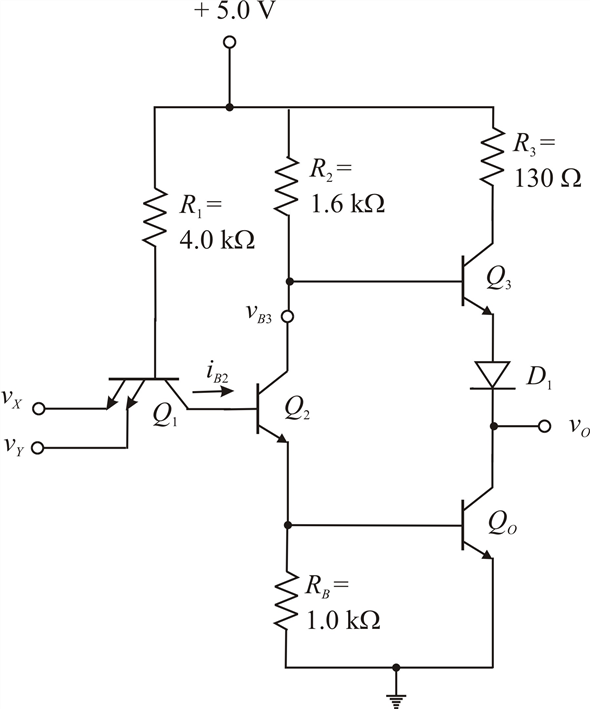

The main difference between the DTL and TTL logic families lies in the operational speed. Now the output voltage is high approximately +5 V. This drives the transistor T1 to cut-off. The charge stored at the base of the transistor T3 does not leak through the resistor instead flows across the forward-biased collector-base junction of transistor T1. When the input voltage is low, then the base-emitter voltage VBE is more than zero thereby making the current flow through the base resistor to the emitter-base junction of T1 and then to the ground. Transistor T3 is saturated and the output of the gate is 0.2 V. It later passes through the collector-base junction of T1 and into the base of transistor T3. The current from VCC will flow across the base resistor RB. The base-emitter voltage is less and the base-collector voltage, VBE, will be more than zero. When the input voltage is high, then transistor T1 will be in the reverse active region.

Let us first consider the working of the basic TTL gate. The circuit of the basic Transistor-Transistor Logic (TTL) gate is shown in the figure below. Working of Transistor-Transistor Logic (TTL) It is also known as T 2L family and was introduced by Texas Instruments in 1964. Transistor-Transistor Logic is the most popular and widely used IC logic family. The NAND gate is the basic building block of this logic family. It is a logic family implemented with bipolar process technology that combines or integrates NPN transistors, PN junction diodes, and diffused resistors in a single monolithic structure to get the desired logic function. TTL as outlined above stands for Transistor-Transistor Logic.

Working of Transistor-Transistor Logic (TTL).


 0 kommentar(er)
